
Industrial equipment foundations and supporting structures must transmit actions safely into the ground or the wider structure while controlling movements compatible with operation. Structural resistance alone does not establish acceptable vibration performance. A workable scheme brings together the equipment supplier, structural and geotechnical engineers, the operator and appropriately qualified dynamic specialists where required, with performance criteria and design responsibilities agreed before detailed design.
1. Foundations and supporting structures for industrial equipment
Examples include induced-draught and forced-draught fans, industrial blowers, pumps, compressors, motors, generators, process equipment and skids, tanks and vessels. Equipment may sit on a ground-bearing machine block, an existing industrial foundation, a steel support frame or an elevated slab. The support system and its interaction with connected pipework, ducts and services matter as much as the concrete block itself.
The design considers strength, stability, serviceability and operational compatibility. Movements may affect shaft alignment, seals, bearings, connected services or neighbouring equipment before a structural resistance limit is reached. Static, cyclic and transient conditions must be distinguished, and the required engineering scope established from reliable supplier information.
2. Information required from the equipment supplier
Request a coordinated loading schedule referenced to an agreed datum, support arrangement and sign convention. Equipment mass is a property of the equipment; gravity weight is a force derived from mass, while operational excitation is a separate time-dependent action. A transport weight, operating weight or centre of gravity cannot, by itself, define the dynamic forces applied to the foundation.
- Equipment operating, empty and transport masses or weights, with units and included contents clearly stated; centre of gravity for relevant configurations.
- General arrangement, equipment footprint, support points, baseplate and holding-down bolt layouts, tolerances and proposed grout/interface details.
- Static vertical and horizontal actions and moments at the supports, including eccentricities and any forces from connected pipework, ducts or services.
- Operating speeds, operating range, excitation frequencies and harmonics; unbalanced forces and moments with amplitudes, phase relationships where relevant, directions and reference points.
- Starting, stopping, run-up, coast-down and emergency conditions, including relevant transient forces, torques and duration or cycles.
- Allowable equipment movements and vibration limits, identifying measurement quantity, frequency range, location, operating state and responsibility for acceptance.
- Maintenance, replacement, lifting and temporary configurations; thermal movements and manufacturer-specific foundation requirements.
Missing or inconsistent information must be identified explicitly. Agreed assumptions may be appropriate for an early feasibility study, but their consequences and limitations must be recorded; additional investigation or specialist assessment may be necessary before the design can be completed. Do not silently replace missing dynamic data with a percentage of equipment weight.
3. Static structural design
The static assessment establishes the relevant design situations, actions and combinations under the agreed design basis. It includes permanent equipment and foundation loads, contents, imposed maintenance loads, horizontal actions and overturning moments. Loads may act eccentrically; a central vertical equipment weight is not a sufficient model for an eccentric skid, elevated machine or vessel subject to lateral actions.
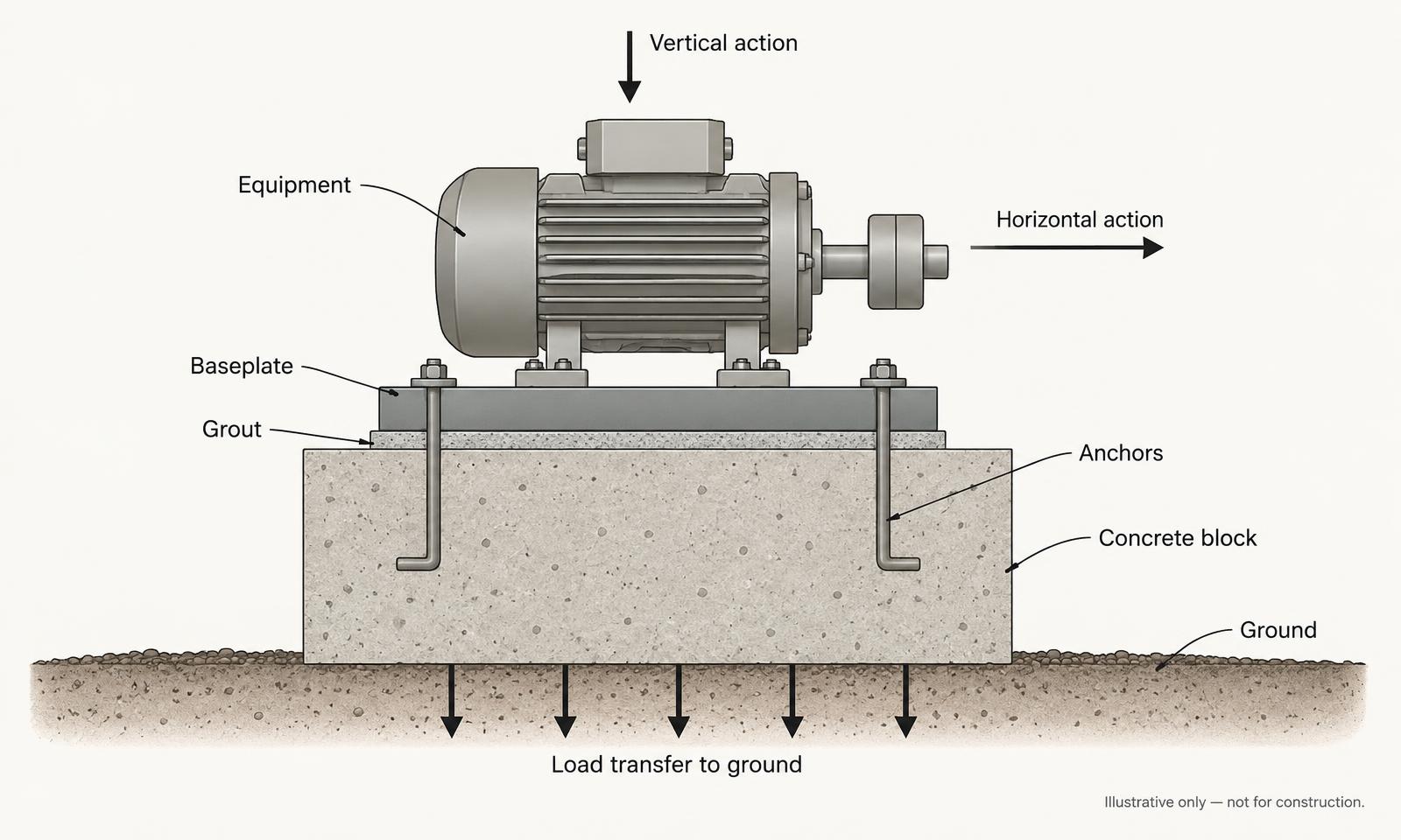
Trace forces through equipment feet, baseplate, grout, anchors, concrete, supporting frame or slab and into the ground. Check resistance and serviceability at each interface rather than treating the foundation as an isolated weight. Sliding, uplift, overturning and bearing assessments depend on the actual contact and restraint conditions; resistance components must not be counted twice or assumed without justification.
- Bearing pressures, ground resistance and settlement under relevant eccentric loading and contact conditions.
- Reinforced-concrete flexure, shear and punching shear where applicable; local bearing, discontinuity regions and force transfer around anchors.
- Anchor tension and shear, baseplate bending, grout/interface behaviour and their effects on the concrete block.
- Foundation stability, supporting slab/frame capacity, deformation and the continuing load path.
- Construction and maintenance situations, durability and environmental exposure, access and future replacement.
4. Dynamic behaviour and machine-induced vibration
Rotating and reciprocating machinery can apply periodic forces and moments, often at several frequencies. The running speed is not necessarily the only excitation: harmonics, reciprocating mechanisms and process effects may be important. Starting and stopping can pass through different response conditions from steady operation.
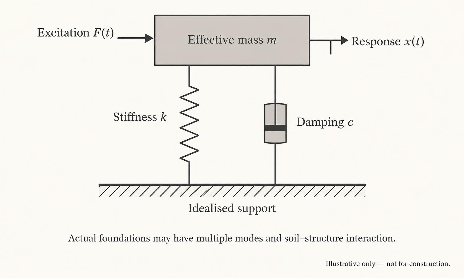
Natural frequencies and mode shapes describe how the equipment, foundation and supporting system can move. Resonance can produce increased response when an excitation interacts with a relevant natural mode. Damping dissipates energy and influences response, but must be supported by an appropriate model or evidence rather than chosen solely to obtain a favourable result. Dynamic amplification depends on frequency, damping, modal participation, loading and boundary conditions.
A static structural assessment checks resistance and deformation under its defined actions. A dynamic assessment evaluates response to time-varying excitation and its consequences for operation, fatigue, ground response and neighbouring structures. The need and level of dynamic analysis are determined by the equipment, supports, operating envelope and performance requirements; not every installation needs the same modelling approach.
A generic multiplier applied to equipment self-weight is not, by itself, a reliable substitute for assessing the actual dynamic forces and structural response of vibrating machinery.
This guide prescribes no universal foundation-to-equipment mass ratio or frequency-separation percentage. Where such criteria are adopted, justify them against the equipment requirements, relevant engineering guidance and project-specific analysis. Consider the full speed range, harmonics and transients rather than a single operating point. Coordinate specialist assessment where vibration transmission to adjacent structures, sensitive processes or occupied areas is relevant.
Mass, stiffness, damping and excitation — an idealised model
5. Foundation mass, stiffness and soil–structure interaction
Foundation mass, geometry and stiffness interact with the equipment, ground and any structural restraint. Increasing mass does not necessarily solve a vibration problem: it can shift natural frequencies and alter rocking or translational response, while increasing ground pressures and settlement demand. Changes in stiffness, geometry or restraint can also move a mode into or out of an excitation range.
Traditional rules of thumb can support an initial option appraisal only when their scope and limitations are understood. They do not replace an adequate loading schedule, defined acceptance criteria or a justified analysis. Ground stiffness and damping may vary with frequency, strain level and soil conditions; soil–structure interaction can be important for ground-bearing blocks and piled systems.
Isolation from neighbouring slabs or supports may reduce some transmission paths but is not automatically beneficial in every frequency range. Isolation joints, resilient systems and connected services must be coordinated with the supplier and specialist, including their effect on stability, movement and alternative transmission paths.
6. Ground-bearing foundations and machine blocks
Ground investigation should establish the ground profile and parameters relevant to bearing, total and differential settlement and, where needed, dynamic behaviour. A quoted allowable bearing pressure without its basis, settlement assumptions or applicable conditions is not a complete foundation design input. Fill, groundwater, contamination, adjacent foundations and buried services may influence feasibility and construction.
Select block dimensions and founding level from the actual actions, contact conditions, ground response and required operational movements. Eccentricity and overturning can change the contact-pressure distribution; sliding resistance and uplift require a justified load path. Reinforcement and local detailing must develop forces around anchors and other concentrated actions and address the relevant durability and crack-control requirements.
Construction joints, grout specification, anchor tolerances, concrete placement and curing, access and maintenance must be coordinated. Where separation from an adjacent slab is intended, define the joint and check that services, finishes or subsequent works do not unintentionally bridge it. The illustration is not a construction or anchorage detail.
Ground-bearing machine block — conceptual load transfer
7. Piled equipment foundations
Piles may be appropriate for poor or variable ground, significant actions or overturning moments, restrictive settlement criteria, or constraints around existing structures and services. Their feasibility depends on the ground, installation method, access, buried obstructions and effects on nearby assets; piling is not an automatic solution to every heavy machine installation.
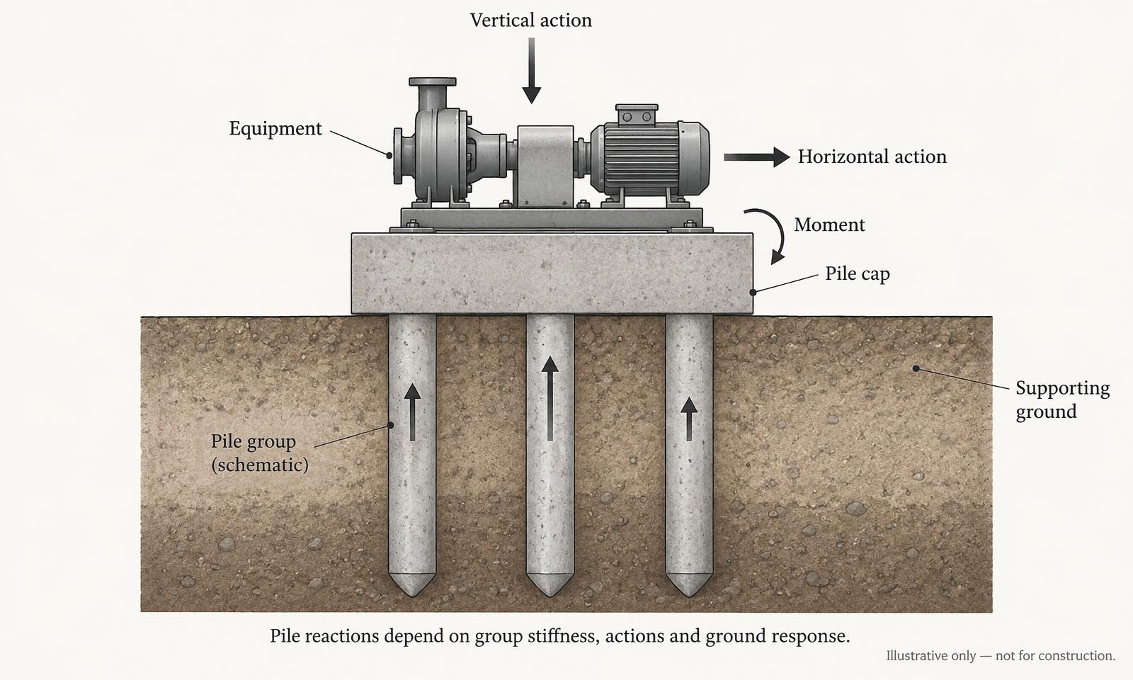
Assess the pile group as a system. Cap stiffness, pile axial and lateral response, group interaction and the ground govern load distribution and deformation. Where relevant, dynamic soil–pile interaction and group stiffness must be included in the specialist assessment. Pile-cap design must transfer equipment and anchor actions into the actual pile arrangement, with the force-transfer model and reinforcement detailing resolved.
A piled foundation does not automatically eliminate vibration concerns. It can transmit vibration into other ground layers or connected structures, and the combined equipment-cap-pile-ground system still has dynamic characteristics. Acceptance criteria and any testing or monitoring requirements must be agreed by the responsible parties.
Piled equipment foundation — actions and pile-group response
8. Equipment mounted on existing slabs or structures
Existing reinforced-concrete slabs, suspended floors, steel gantries, elevated plant platforms and industrial foundations require verification rather than an assumption of spare capacity. Establish as-built geometry, reinforcement or steel details, materials, support conditions, foundations and the route by which the new actions reach the ground. Survey records, inspection, opening up or testing may be required where drawings or condition are uncertain.
Check the existing condition, corrosion or deterioration, earlier alterations and cumulative loads. Local bearing, punching, anchors and edge distances may govern even where the overall slab or frame appears substantial. Strength, deflection, fatigue where relevant and vibration characteristics must be considered for the proposed operating conditions.
Suspended or elevated supports can be more flexible than a ground-bearing block, with several structural modes and interactions with other equipment. A satisfactory static capacity check does not demonstrate acceptable vibration response. Any assumed isolation, restraint or beneficial contribution from adjacent members must be established, not inferred from appearance.
9. Holding-down bolts, anchors, baseplates and grout
Cast-in holding-down bolts and post-installed mechanical or bonded anchors require a design matched to their intended use. Resolve baseplate stiffness, grout and contact assumptions, tension and shear distribution and the transfer of forces into the concrete. Consider group behaviour, concrete breakout and other relevant failure modes, edge distances, spacing, concrete condition and the effects of combined actions.
BS EN 1992-4 addresses design of fastenings for use in concrete within its scope. Product-specific assessment and manufacturer installation requirements remain essential; an ETA or other applicable approval and its declared characteristics must be checked for the proposed substrate, environment and loading. Do not assume that approval for one loading category establishes suitability for fatigue or repeated machine actions.
Where cyclic loading or fatigue is relevant, establish a suitable assessment method and qualified anchor system. Consider installation tolerances, drilling and cleaning procedures, embedment, tightening or curing requirements, inspection and the effects of rebar, cracks and services. The structural appointment should state who specifies, installs, inspects and verifies anchors. No universal capacity or embedment is supplied here.
10. Design standards and project applicability
A project design basis must identify applicable British Standards, Eurocode editions and UK National Annexes, amendments and equipment-specific requirements. The newest catalogue edition is not automatically the edition applicable to an existing contract or assessment. Second-generation Eurocodes are being introduced while first-generation documents and National Annexes remain relevant during the transition; do not mix generations or select isolated favourable provisions without a coherent justified basis.
BS EN 1990 and its applicable UK National Annex establish the structural design basis. Select relevant BS EN 1991 parts for actions, BS EN 1992 parts for concrete, BS EN 1993 parts for steel and BS EN 1997 parts for geotechnical design according to the actual structure and scope. BS EN 1991-3 addresses actions induced by cranes and machinery within its scope; supplier actions and specialist analysis are still required where that scope or its simplified treatment is insufficient.
BS EN 1992-4 is relevant to concrete fastenings within its stated scope. Connections, fatigue and other specialist checks may require further material standards and guidance appropriate to the design situation. Ground investigation and dynamic soil parameters must be appropriate to the analysis, not simply inferred from a general bearing value.
The ISO 20816 series concerns measurement and evaluation of machine vibration; select the applicable part for the particular machine, power, speed, support conditions and measurement method. These are not complete structural foundation design standards. The ISO 21940 series addresses rotor balancing, with different parts for rigid and flexible rotor behaviour; balancing data or compliance does not itself establish a foundation design or vibration performance prediction.
BSI’s published coexistence notice states that first-generation Eurocodes should be considered applicable to UK buildings and civil engineering works until 30 March 2028 unless the relevant authority or project specification states otherwise. Second-generation publications include BS EN 1990-1:2023+A1:2026 and its UK National Annex, BS EN 1991-3:2026, BS EN 1992-1-1:2023, BS EN 1993-1-1:2022 and BS EN 1993-1-8:2024, and BS EN 1997-1:2024, BS EN 1997-2:2024 and BS EN 1997-3:2025. Their publication does not establish a complete compatible project basis or National Annex set for every application.
The ISO catalogue identifies ISO 20816-1:2026 and ISO 20816-3:2026 as October 2026 editions replacing the earlier general and industrial-machine editions. ISO references are stated as ISO publications here; corresponding British adoption of these revisions has not been verified. ISO 21940-11:2016 must be read with its 2022 amendment, while ISO 21940-14:2026 replaces the earlier balance-error edition. Select other machine-specific parts from the actual scope, not a generic equipment label.
The linked official BSI and ISO records below provide reference and scope information, not the full design provisions. Final selection, current amendments, UK National Annex compatibility and contract/regulatory applicability must be checked before approval. National Annex amendment histories for the additional action/material parts have not been exhaustively checked, and no claim of full standards compliance is made. Recognised specialist machine-foundation guidance may supplement, not override, the agreed UK design basis and supplier requirements.
11. Typical BES engineering services and specialist interfaces
Subject to the agreed appointment, available information and project requirements, BES may provide the following structural engineering services. The proposal defines deliverables, investigation requirements, assumptions, exclusions and construction-stage involvement.
- Review of manufacturer loading information and existing structural assessment.
- Foundation feasibility and option appraisal; ground-bearing reinforced-concrete foundation and pile-cap design.
- Structural steel support-frame design, anchor and baseplate design within the agreed scope.
- Coordination with equipment suppliers and geotechnical engineers; review of specialist dynamic-assessment information for structural interfaces.
- Project-specific structural calculations and drawings.
Where specialist dynamic analysis is needed, coordinate appropriately qualified specialists with clear responsibilities for modelling, input data, vibration criteria and acceptance. BES does not claim independent vibration testing, rotor dynamics or machinery balancing. Plant supply, installation and construction contracting are not offered. The equipment supplier and appointed specialists must resolve machine-specific performance matters; structural design does not guarantee equipment performance outside its agreed basis.
12. Project information checklist
Provide a clear equipment brief and the available records early. The BES Project Information Checklist / Builder helps assemble an enquiry; it does not replace supplier loading data, ground investigation or an engineering assessment. Use the related checklist and commercial/industrial service links below to prepare the initial discussion.
- Equipment type, manufacturer, model and intended process or duty; equipment datasheets.
- General arrangements, support and anchor layouts, relevant equipment dimensions and interface drawings.
- Operating, transport and other relevant weights or masses, units, centre of gravity and load reference points.
- Operating speed range, dynamic forces and moments, harmonics and starting/stopping/emergency data.
- Agreed movement and vibration criteria, measurement arrangements and responsibility for acceptance.
- Existing foundation, slab and frame drawings, earlier calculations and condition information.
- Ground investigation, site photographs, buried services and adjacent asset information.
- Programme, shutdowns, lifting, access, maintenance and operational constraints; named supplier and specialist contacts.
13. Reading the illustrative diagrams
The three figures show conceptual relationships only: equipment-to-ground load transfer through a machine block; an idealised mass–stiffness–damping model; and actions carried by a piled cap and group. They are shared by the webpage and both downloads. Proportions are for explanation, not sizing, and do not establish reinforcement, anchor capacities, pile count or construction arrangements.
Read every figure with its caption and the limitations. A single-degree-of-freedom drawing is not evidence that a real machine-foundation system has only one mode. Ground pressures and pile reactions are determined by the project model; the illustrated arrows are not calculated distributions. No drawing here authorises installation or construction.
Common questions
Does all rotating equipment require a dynamic foundation assessment?
Not every installation needs the same level of analysis. Establish the equipment excitation, operating range, support flexibility and performance criteria. A competent engineer and, where required, a dynamic specialist determine whether a simplified assessment is adequate or a more detailed model is needed; static adequacy alone does not settle vibration performance.
Can a machine foundation be designed using a static load multiplier?
A generic multiplier on equipment self-weight does not, by itself, reliably represent machine excitation or structural response. Any simplified loading approach needs an applicable basis, justified supplier data and a clear scope; actual dynamic forces, frequencies, modes and damping must be considered where relevant.
How heavy should a machine foundation be?
There is no universal foundation-to-equipment mass ratio. Determine mass, geometry and stiffness from the actions, ground response and operational criteria. Adding mass can change natural frequencies and increase bearing or settlement demand rather than solve the problem.
When might piled foundations be required?
They may be appropriate for poor or variable ground, high actions or overturning, settlement restrictions or site constraints. Feasibility, pile-group response and cap design need assessment; piles do not automatically remove vibration concerns.
Can equipment be installed on an existing concrete slab?
Only after the existing construction, condition, supports and load paths are established and capacity, local anchor/bearing effects, serviceability and relevant vibration response are checked for the proposed equipment. A substantial-looking slab is not proof of suitability.
What information is required from the equipment manufacturer?
Provide masses or weights and units, centre of gravity, support and anchor layouts, static actions, operating speed range, dynamic force and moment data, transients, allowable movements and vibration criteria, plus maintenance and thermal/interface requirements. Identify loading reference points and unresolved data explicitly.
Who is responsible for vibration performance criteria?
Agree this expressly between the operator, equipment supplier and appointed engineering/dynamic specialists. Define acceptable quantities, locations, operating states and verification arrangements. BES addresses the structural interfaces within its appointment; a structural calculation does not assign or guarantee all machine-performance criteria.
Official standards references — UK design basis and ISO scope
- BSI — BS EN 1990:2002+A1:2005, first-generation basis of structural design (project applicability to be agreed)
- BSI — NA to BS EN 1990:2002+A1:2005, corresponding UK National Annex
- BSI — BS EN 1991-1-1:2002, densities, self-weight and imposed building loads
- BSI — BS EN 1991-3:2006, actions induced by cranes and machinery (first generation)
- BSI — BS EN 1992-1-1:2004+A1:2014, concrete general rules (first generation)
- BSI — BS EN 1993-1-1:2005+A1:2014, steel general rules (first generation)
- BSI — BS EN 1993-1-8:2005, steel joints (first generation)
- BSI — BS EN 1997-1:2004+A1:2013, geotechnical general rules (first generation)
- BSI — BS EN 1997-2:2007, ground investigation and testing (first generation)
- BSI — BS EN 1992-4:2018, design of fastenings for use in concrete
- BSI — NA to BS EN 1992-4:2018, UK National Annex (published 2019; the standard remains designated 2018)
- BSI — BS EN 1990-1:2023+A1:2026, second-generation new-structures basis and UK coexistence notice
- BSI — NA to BS EN 1990-1:2023+A1:2026, second-generation UK National Annex
- BSI — BS EN 1991-3:2026, second-generation actions induced by cranes and machines
- BSI — BS EN 1992-1-1:2023, second-generation concrete general rules
- BSI — BS EN 1993-1-1:2022, second-generation steel general rules
- BSI — BS EN 1993-1-8:2024, second-generation steel joints
- BSI — BS EN 1997-1:2024, second-generation geotechnical general rules
- BSI — BS EN 1997-2:2024, second-generation ground properties
- BSI — BS EN 1997-3:2025, second-generation geotechnical structures
- ISO — ISO 20816-1:2026, machine vibration measurement and evaluation: general guidelines (not a foundation design standard)
- ISO — ISO 20816-3:2026, industrial machines with operating speeds between 120 r/min and 30 000 r/min; check complete scope and exclusions
- ISO — ISO 21940-11:2016, procedures and tolerances for rotors with rigid behaviour
- ISO — ISO 21940-11:2016/Amd 1:2022, amendment to rigid-rotor balancing procedures
- ISO — ISO 21940-12:2016, procedures and tolerances for rotors with flexible behaviour
- ISO — ISO 21940-13:2012, criteria and safeguards for in-situ balancing of medium and large rotors
- ISO — ISO 21940-14:2026, procedures for assessing balance errors
- ACI — PRC-351.3-18, Report on Foundations for Dynamic Equipment (supplementary non-UK guidance; not a UK design standard)
Check applicable editions and transitional provisions for the project.
Key considerations
- Obtain reliable supplier actions and distinguish mass, gravity weight and dynamic excitation.
- Agree operational criteria and specialist responsibilities before detailed design.
- Assess the complete equipment–support–ground load path, including existing construction and anchors.
- Use a coherent project design basis; do not mistake machinery vibration acceptance standards for foundation design standards.
- No universal mass ratio, frequency separation, self-weight multiplier or construction detail replaces project-specific engineering.
Related BES tools and services
Related guidance
- BES-TG-006Structural Engineering for Industrial Building AlterationsRead →
- BES-TG-005What Information Does a Structural Engineer Need?Read →
- BES-TG-008Temporary Works ExplainedRead →
- BES-TG-007Steel Beam Design ExplainedRead →
- FAQCan BES inspect industrial buildings?Read →
- FAQWhat information is required for a quotation?Read →
Discuss your equipment foundation project
General guidance only goes so far. Describe your building and what you are planning, and you will receive project-specific advice from a Chartered Structural Engineer.
Important limitations
General structural engineering guidance only, not a project-specific design, certification, vibration assessment or construction specification. Equipment actions, operating envelopes, ground parameters, structural condition and performance criteria require verification for the individual installation. No universal mass ratio, frequency-separation criterion, self-weight dynamic multiplier, anchor capacity, reinforcement size or design dimension is supplied. Illustrations are not for construction. Applicable standards, UK National Annexes, amendments and assessment methods must be agreed for the project. Specialist vibration testing, dynamic modelling, rotor dynamics and machinery balancing require appropriately qualified separate specialists; BES coordinates or reviews their information only within the agreed appointment. BES does not offer plant supply, installation or construction contracting.
BES-TG-014 · Version 1.0 · Published 1 November 2026 · Next scheduled review Not scheduled