
Removing a wall changes more than the shape of a room. It can redistribute gravity loads, remove restraint and change the stiffness of a building. This detailed companion to BES-TG-002 focuses on the evidence and engineering decisions needed to develop a complete alteration scheme: what must be investigated, which checks depend on the proposed arrangement and where responsibilities must be coordinated. It is not a beam-sizing manual or a method statement. Its regulatory discussion relates to England and must be checked for the particular property and proposal.
1. What the wall does — gravity loads and restraint
A load-bearing wall receives load from other parts of a building and passes it to a supporting element below. Floor joists, roof members, walls above, chimney structures and concentrated reactions from beams or columns may all contribute. These loads need not be directly above the proposed opening: a beam elsewhere may deliver a reaction into the wall, and an earlier alteration may have redirected the original load path.
A wall can also buttress another wall, restrain an external masonry panel or participate in the building’s resistance to horizontal actions. Removing a wall that carries little apparent gravity load can therefore still have structural consequences. Thickness, sound when tapped or masonry versus timber construction do not establish that a wall is safe to remove.
The initial question is not simply “is it load-bearing?” but “which functions will be lost, and how will each be replaced?” Record the existing arrangement and the intended extent of removal, including retained returns, connections to adjacent walls and any other openings proposed at the same time.
2. Identifying the wall’s role — evidence, not a definitive test
Joist direction, walls continuing between storeys, roof supports and visible beam positions are useful indicators, not conclusive tests. Joists may run parallel to a wall that supports a wall above or a concentrated beam reaction. A perpendicular joist arrangement does not prove bearing: the joists could bridge the wall or be supported elsewhere. Concealed trimmers and changes of span can make the apparent arrangement misleading.
Drawings and building history help frame an investigation, but an old drawing may describe an intended scheme rather than the construction now present. Compare drawings with site observations, record known alterations and distinguish verified facts from assumptions. Masonry condition, bonding at junctions and wall thickness are assessed as part of the wider evidence, not used as standalone identification rules.
Inspection from accessible locations may leave critical bearings, connections or wall continuity concealed. Selective opening up can be needed, with safe access, services and asbestos considerations addressed before disturbance. A feasibility opinion based on limited evidence should identify what must be confirmed before the design is relied on for construction.
3. Load paths — from distributed support to concentrated reactions
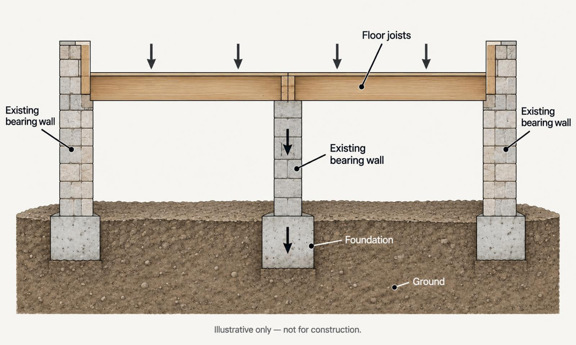
Loads from floors, roofs and walls must be traced through the proposed beam, its bearings or connections, retained masonry or columns, lower-storey structure and foundations to the ground. The load take-down should distinguish the loads from different sources and account for the actual spans and support arrangement. The total load and its position matter: an opening of the same width in another house can have a very different structural demand.
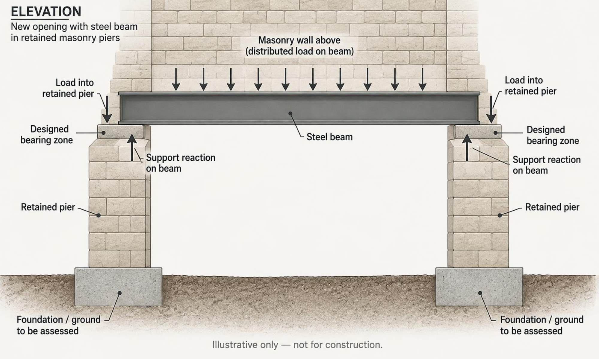
A wall commonly distributes load along its length. Replacing part of that wall with a beam collects load and introduces concentrated end reactions. Those reactions need not be equal: eccentric loading, a point load or a different support arrangement can produce markedly different demands at the two ends. The drawing should make the intended support points clear.
Consider what lies below each reaction. A pier may sit above another opening, a suspended floor or an earlier beam rather than a continuous wall and footing. A successful beam check does not establish adequacy of that downstream structure. Changes in movement or stiffness also matter where brittle masonry, finishes or adjoining structures are retained.
Existing floor support — distributed load path
4. Steel beam arrangements and design interfaces
Possible arrangements include a single universal beam, paired beams, a member carrying masonry and joists together, or a beam-and-column system. These are options to assess, not interchangeable details. A paired arrangement needs a defined means of distributing load and, where assumed, making the members act together. Do not assume two unconnected members automatically share load equally. Multiple-storey or intersecting-beam loads can require different supports and connections.
Calculations address bending and shear resistance together with deflection and the serviceability of the supported construction. Lateral restraint, lateral-torsional stability and the positions where restraint is effective must correspond to the actual details. Local web or bearing effects, connection actions and eccentricity are considered where relevant. A member must be adequate both for the loads and for the assumed support and restraint conditions.
The architectural and structural design must resolve joist levels, masonry support, connections, service penetrations and fire protection. A floor or ceiling touching a beam is not automatically an adequate lateral restraint or a fire-protection system. Notches, holes, substitutions and changes to levels or bearing positions should not be made without the responsible designer’s assessment. This guide supplies no universal member-size tables.
New opening — beam reactions and continuing load path
5. Bearings and padstones — more than a nominal contact length
Required bearing length and the form of support are determined by the reaction, beam geometry, masonry or concrete properties, local condition and the complete load-transfer arrangement. A padstone or bearing plate can spread contact pressure, but it does not make a weak or slender pier adequate merely by being larger. Eccentricity, edge proximity, cracking, voids and poor bedding can affect how the reaction enters the support.
Assess retained pier dimensions, bonding to adjoining walls, returns, openings nearby and the direction of load. Local crushing is only one issue; pier stability and resistance to combined axial load and bending may also govern. For cavity walls or different wall leaves, the intended load distribution and support to each part must be defined rather than assumed.
Drawings should identify the designed bearing zone and any condition checks needed before concealment. Site discoveries of loose masonry, altered geometry or unsuitable support require review. There is no universal padstone size or bearing length in this guidance, and a padstone is not a substitute for verifying the construction below it.
6. Foundations, supporting walls and new columns
Existing foundations should be considered where reaction redistribution could materially affect their performance. Evidence may include drawings, ground information, condition observations and appropriately planned trial holes. The engineer assesses what is needed; excavation next to existing supports must not itself undermine stability or disturb services.
A new column replaces one support problem with a concentrated load path that requires its own checks. Its base, connections and foundation need to resist the relevant actions, including moments or horizontal loads where present. A column cannot be assumed to bear safely on an ordinary floor slab, and a wall at a lower level may be interrupted by a concealed opening.
Foundation strengthening or local underpinning is not automatically required. Existing capacity, settlement sensitivity, ground conditions and the proposed load distribution may allow a suitable scheme without it; other schemes may need strengthening or new support. Options should be compared against evidence, neighbouring structures and practical constraints rather than treating strengthening as a standard wall-removal detail.
7. Lateral stability and retained masonry
Wall returns and cross-walls can provide buttressing or restraint to external masonry. Floors and roofs may act as diaphragms where their construction and connections provide the required load transfer. A large opening, loss of a return or several alterations considered together can weaken these functions even if each replacement beam is adequate for gravity loads.
Assess the stability of retained piers and wall panels, how horizontal forces reach stable elements, and whether ties, connections or a designed frame are needed. A beam-and-column arrangement is not automatically a moment-resisting stability frame: its joints, bases and foundations must match the intended behaviour.
Permanent restraint and temporary stability are separate but connected questions. Features relied on in the completed building may be absent during construction. The permanent-works designer’s assumptions need to be communicated so that the temporary works and construction planning do not inadvertently remove essential support.
8. Temporary works — designed interfaces, not generic propping
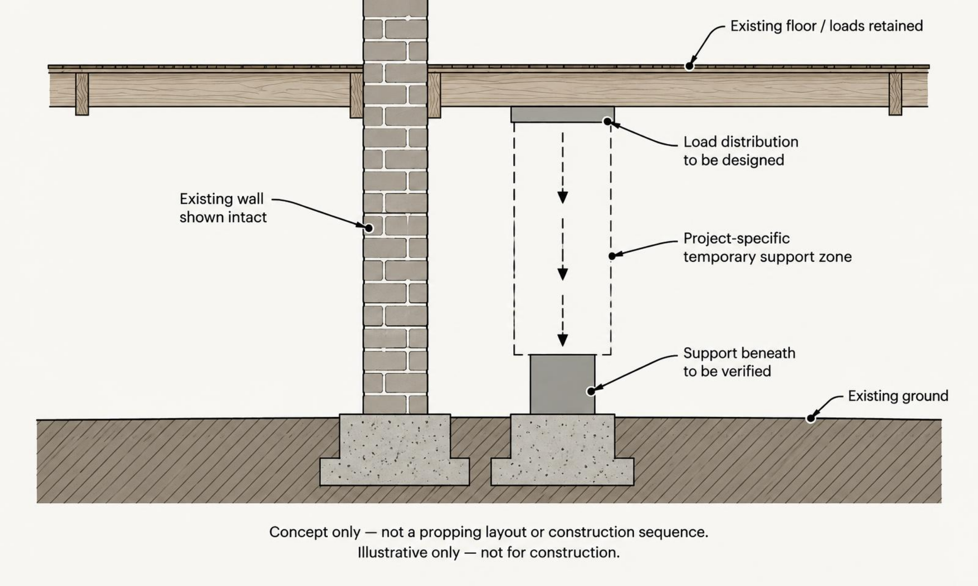
Alteration work must be planned to prevent unplanned collapse and undertaken by competent people. Temporary support may need to sustain floor loads, walls, retained masonry and the beam itself while the permanent load path is incomplete. The construction conditions can differ from the final design; apparent redundancy in the finished arrangement does not establish a safe intermediate condition.
Responsibility for temporary works design, coordination, method statements and site checks must be explicitly allocated in the appointments and contractor arrangements. The contractor plans and carries out the work safely, using competent design input where required. A permanent beam calculation is not automatically a temporary works design. BES construction-stage or temporary-works input applies only where specifically appointed and within the agreed scope.
Resolve load distribution, support beneath temporary systems, lateral stability, retained masonry condition, access, hidden members and services. The construction plan must address the actual stages of work and conditions for loading or removing temporary support. This is not a universal sequence or a list of prop spacings: those decisions belong to the project-specific design and safe method.
Unexpected cracking, movement or different construction from that assumed must be escalated to the responsible parties before the affected work proceeds. A generic illustration or a borrowed arrangement from another job does not demonstrate safe temporary support for this property.
Temporary support — responsibility and load-path concept
9. Building Regulations, planning and listed-building consent
Removing a load-bearing wall or forming a structural opening in England normally requires Building Regulations approval. Part A addresses structural requirements; calculations and drawings are commonly used to demonstrate the adequacy of the proposed arrangement. Confirm the appropriate building-control process and agreed inspection arrangements before work, including which details need to remain visible for inspection. Approval is not supplied by the structural engineer merely by issuing calculations.
Other requirements depend on the affected work. Part B may be relevant to fire resistance, escape arrangements or compartmentation. Part C may matter where moisture protection or relevant ground conditions are changed; Part E may matter where separating construction and sound performance are affected. Other parts can also be engaged by the wider alteration. Structural adequacy alone does not demonstrate compliance with every requirement.
Approved Documents give guidance on meeting functional requirements; use the applicable England guidance and amendment/commencement provisions for the particular project. Publication of a revised document does not by itself establish that all its provisions already apply. This guide does not prescribe a blanket fire-protection or acoustic detail.
Planning permission is distinct from Building Regulations approval. Ordinary internal alterations do not normally need planning permission, but changes affecting external appearance, particular restrictions or the wider proposal can change the position. Works to a listed building that affect its character as a building of special architectural or historic interest may require listed-building consent, including internal work. Seek local planning authority or conservation advice where uncertain; neither planning permission nor listed-building consent replaces structural assessment or Building Regulations requirements.
10. Party Wall etc. Act 1996 — separate statutory procedures
Work affecting a party wall or party structure may fall within the Party Wall etc. Act 1996. Cutting a beam pocket into a party wall is an example that needs specific consideration. The actual work and structure determine whether statutory notices and other procedures are required; not every internal wall or every beam bearing automatically falls within the Act. Certain excavation or foundation work near neighbouring structures can also be relevant.
The building owner should identify the applicable obligations before starting work and obtain suitable party-wall advice where needed. Structural design, Building Regulations and party-wall procedures are separate responsibilities: a calculation package is not a party-wall notice or award, and a neighbour’s informal agreement is not a reason to ignore applicable statutory procedures.
Coordinate the design with any agreed access, information and party-wall requirements. BES structural engineering does not imply appointment as a party-wall surveyor or provision of legal advice. The GOV.UK guidance and the actual provisions of the Act should be considered alongside project-specific specialist advice.
11. Opening up, condition surveys and controlled design changes
A proportionate investigation can include exposing joist ends and beam bearings, confirming wall construction and floor spans, identifying hidden steelwork, checking foundation arrangements and reviewing cracking or movement. Record both the findings and the limits of access. Plan intrusive work with competent people so that investigating the structure does not remove its support or restraint.
Locate services and address possible asbestos-containing materials before disturbance where relevant. Older buildings can contain concealed asbestos; appearance alone cannot clear materials for intrusive work. The scope of an appropriate refurbishment or demolition survey should be set by competent asbestos specialists for the proposed disturbance. A routine management survey is not automatically sufficient for concealed fabric affected by alteration.
Feasibility assumptions should be labelled and their verification requirements agreed. Where a material assumption proves incorrect, the responsible designer should assess the effect and issue any necessary revision before the affected work proceeds. Keep the contractor, architect and building-control body informed as appropriate; a verbal site substitution should not silently replace the design basis.
Agree project-specific inspection and information points, without interpreting this guide as a construction sequence. Keep revised drawings, relevant inspection records and the building-control completion documentation with the property information. Unresolved observations should be recorded rather than represented as accepted or certified.
12. Typical BES scope and the limits of an appointment
Subject to the agreed appointment, BES may provide initial structural appraisal, site inspections, review of proposed alterations, structural calculations, steel beam and bearing design, structural drawings or sketches, and structural information for Building Regulations. Advice during construction, review of discoveries and responses to technical queries depend on the agreed scope and information available.
The appointment should identify what is being assessed, what remains concealed, which investigations are needed, who coordinates temporary works and who provides architectural, fire-safety or other specialist input. Issuing a permanent-works design does not imply continuous supervision of the contractor, certification of concealed work or approval by Building Control.
Structural engineering is distinct from architectural design, building-control approval, party-wall surveying and construction services. BES does not offer steel supply, fabrication, delivery or installation as part of this guide. Project-specific deliverables and limitations should be agreed before relying on any advice.
13. Client information and decisions to resolve
Provide the information available without disturbing the building to obtain it. Unknown details can be recorded as unknown and investigated safely later. Photographs and dimensions support an initial discussion but are not a substitute for verifying critical construction. Use the BES Project Information Checklist and Project Information Builder to organise the submission.
- Property address, approximate age, number of storeys and any listed status or known restrictions.
- Existing floor plans and architectural proposals showing the wall, proposed opening and retained piers or returns.
- Proposed opening dimensions, photographs of both sides, adjacent rooms and relevant upper and lower levels.
- Floor and roof construction where known, existing structural drawings and records of previous alterations.
- Known chimney structures, roof supports, cracking or movement, existing services and survey information.
- Access for inspection, operational/occupation constraints and the appointed architect or contractor contacts.
- Agreed scope for investigation, permanent works, temporary works, approvals, inspections and responding to site discoveries.
Common questions
How do I know whether a wall is load-bearing?
Use a competent assessment of loads, joist and roof support, wall continuity, drawings and alterations. Direction, thickness or material alone is not definitive. Concealed construction may need safely planned investigation.
Do I need a structural engineer to remove a wall?
Where structural support or stability may be affected, competent assessment and design are needed. A structural engineer can establish the role of the wall and the complete replacement load path; uncertainty should be resolved before alteration.
Do I always need a steel beam?
No. The appropriate scheme may use another designed material or arrangement, or retain part of the wall. Steel is common, but suitability depends on loads, geometry, restraint, fire requirements and supports.
Can a load-bearing wall be removed without a beam?
Not simply because a beam is inconvenient. Its loads and any stability function need a verified alternative arrangement. A different structural solution may be possible, but do not remove the wall without project-specific assessment and design.
What is a padstone?
A designed bearing element used to distribute a concentrated reaction into supporting construction. It does not automatically make weak masonry, a slender pier or an inadequate foundation safe; the complete support must be assessed.
Will the existing foundations need strengthening?
Not necessarily. The answer depends on the redistributed reactions, existing foundation and ground, condition and settlement sensitivity. Investigation may be required before deciding whether the existing support is adequate.
Do I need Building Regulations approval?
A load-bearing wall alteration in England normally requires Building Regulations approval. Confirm the process and inspection arrangements with the relevant building-control body. Planning and other statutory procedures are separate.
Can I remove a chimney breast at the same time?
Only as part of a specific assessment of the chimney and remaining stack, flues, supports, restraint and any shared-wall implications. Combining alterations can change the load path and temporary stability; this guide gives no standard chimney support detail.
Who designs the temporary propping?
The responsibility must be explicitly allocated to competent parties within the contractor and appointment arrangements. The contractor must plan safe construction and obtain suitable temporary works design where needed. A permanent beam design or this diagram is not a propping design.
Can I remove a wall in a listed building?
Seek appropriate conservation and planning advice before work. Internal alterations affecting the building’s special architectural or historic character may need listed-building consent; structural design and Building Regulations remain separate considerations.
Official references — England
- GOV.UK — Approved Documents (England; check applicable editions and amendments)
- Building Regulations 2010 — Schedule 1 functional requirements
- Planning Portal — Internal walls: Building Regulations
- Planning Portal — Internal walls: planning permission
- GOV.UK — Party walls and building work
- GOV.UK — Work you must tell your neighbour about
- HSE — Structural stability during alteration
- HSE — Arranging an asbestos survey
Check applicable editions and transitional provisions for the project.
Key considerations
- Establish every gravity-load and restraint function before selecting a replacement scheme.
- Trace unequal and concentrated reactions through bearings, piers, lower structure and foundations.
- Specify actual restraint and connections rather than relying on assumed beam or frame behaviour.
- Allocate temporary works and investigation responsibilities; confirm material assumptions and manage discoveries.
- Keep structural design, Building Regulations, planning/listed consent and party-wall procedures distinct.
Related BES tools and services
Related guidance
- BES-TG-002Removing a Load-Bearing Wall: A Structural Engineer's GuideRead →
- BES-TG-007Steel Beam Design ExplainedRead →
- BES-TG-008Temporary Works ExplainedRead →
- BES-TG-010Foundations for Building Alterations and ExtensionsRead →
- BES-TG-013Loft Conversions: A Structural Engineer’s GuideRead →
- FAQCan I remove a load-bearing wall?Read →
- FAQDo I need Building Regulations approval?Read →
Discuss your wall-removal project
General guidance only goes so far. Describe your building and what you are planning, and you will receive project-specific advice from a Chartered Structural Engineer.
Important limitations
General information only; this guide does not replace project-specific structural assessment, design or temporary works advice. No illustration is a construction detail, propping layout, installation sequence or authority to alter a building. Member sizes, bearings, padstones, foundations, restraint, fire protection and construction stages require competent project-specific assessment and coordination. Regulatory information concerns England and is not legal advice; applicable requirements, consents and guidance editions must be confirmed for the actual work.
BES-TG-015 · Version 1.0 · Published 1 November 2026 · Next scheduled review Not scheduled